Woven Table
In this self-directed, experimental project I explored how I could use modern form-making technology to reinterpret an indigenous craft practice. Furthermore, I investigated how to design furniture that unifies traditional woodworking with cutting-edge additive manufacturing.
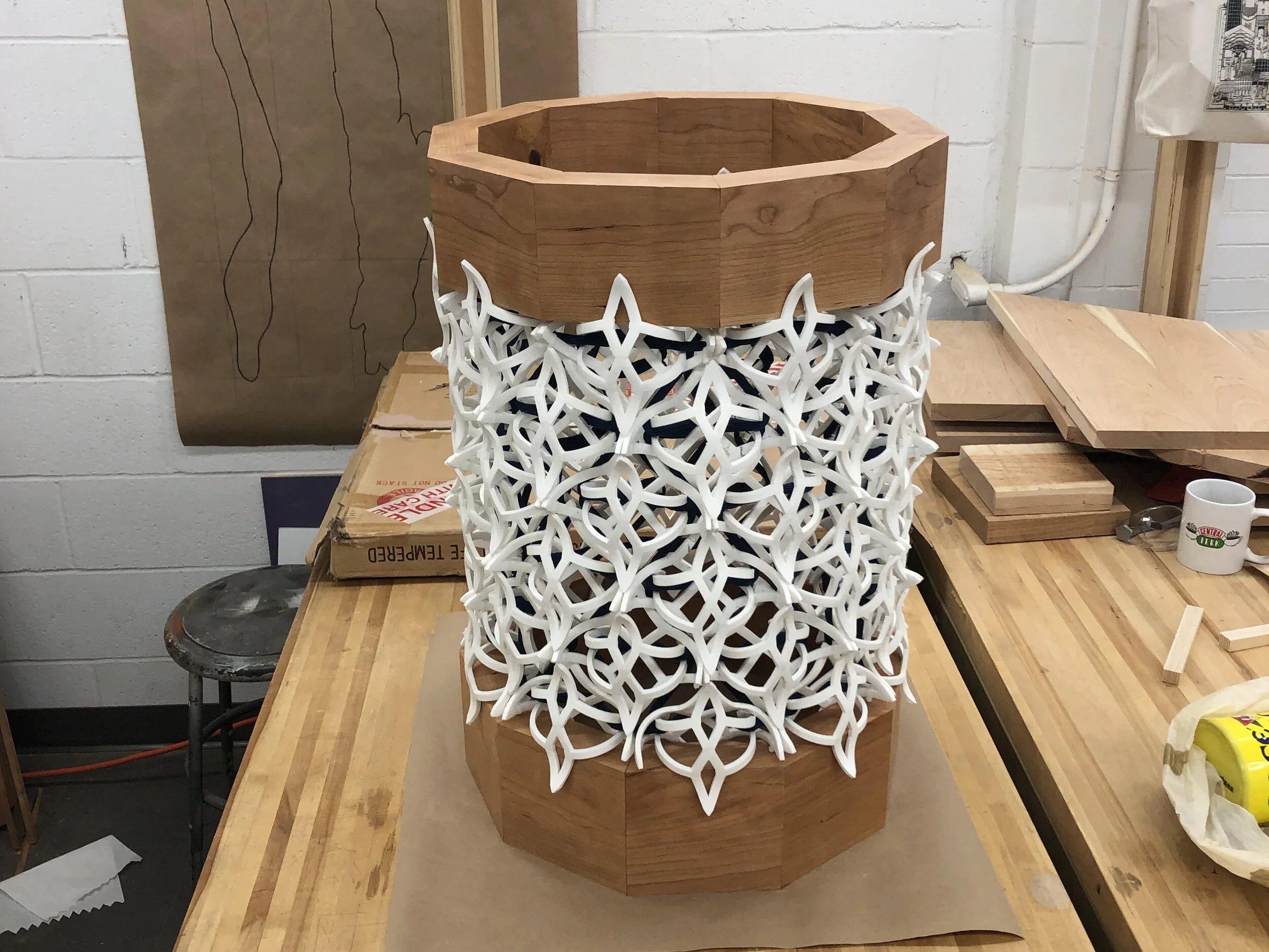
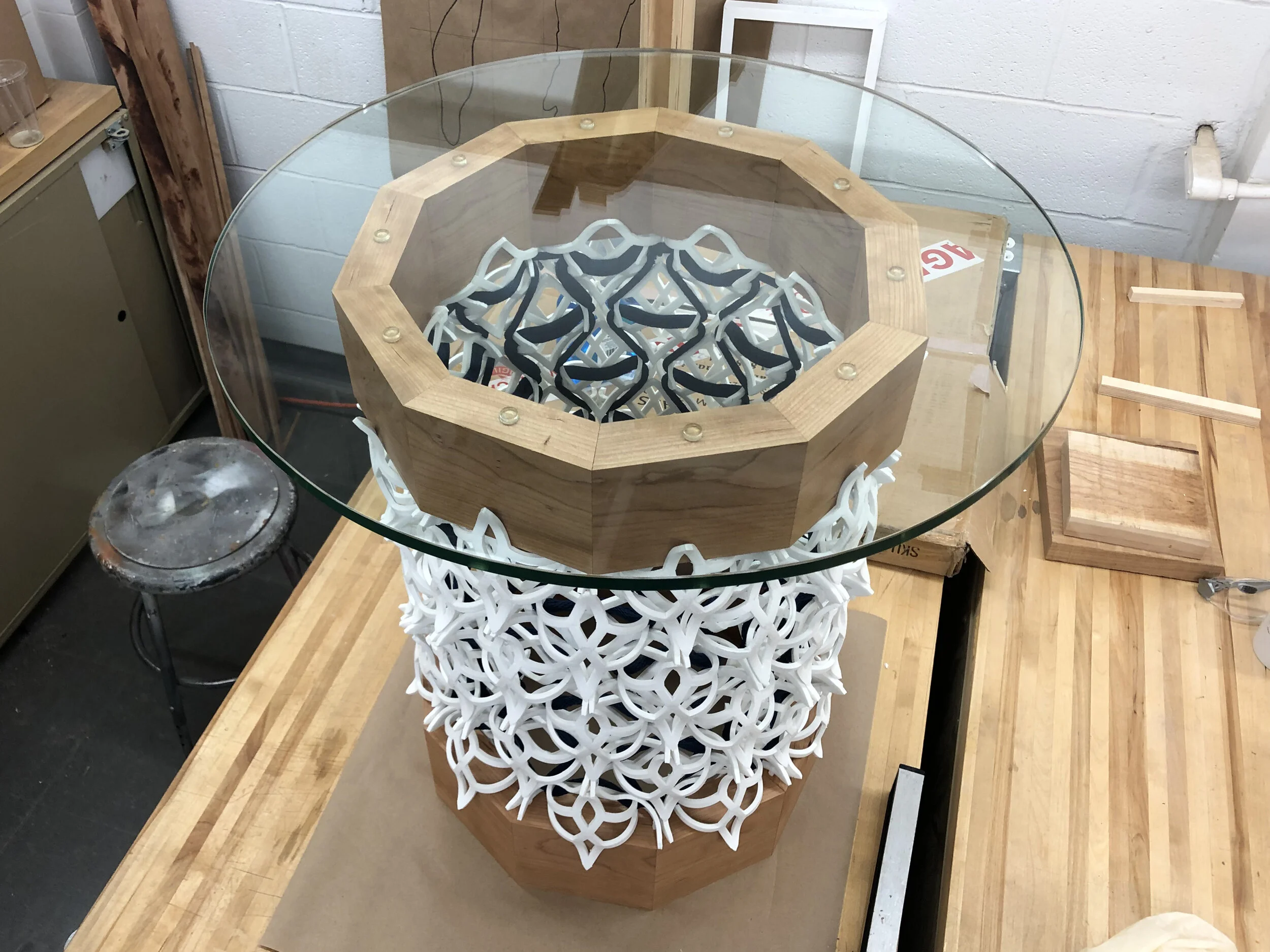
The body of the table is an aggregate structure of 120 interlocking parts made of 4D-printed thermoplastic. This assembly is woven together using a traditional Native American bead weaving technique. The form is captured by two wooden rings, and completed with a glass tabletop.
Concept Development
The initial prompt for this project was to design some sort of aggregate structure using 4D-printed parts—ones that are 3D-printed flat, and then morph into predetermined shapes when submerged in hot water—that conform to a 2x2 grid. This prompt was very open, but got me thinking about where I’d encountered an aggregate structure in my past experiences making things.
Years before this project began, I was introduced to many different Native American craft practices. One I spent a long time exploring was beadwork, which included the peyote stitch: a tubular, off-loom weaving technique for seed beads. I had the idea of scale up this cylindrical weaving technique to lash together 4D-printed units that would be diamond-shaped (so as to conform to a 2x2 grid).
Example of my experience with beadwork
Diagrams explaining peyote stitch variations
Adaptation into larger-scale diamond pattern
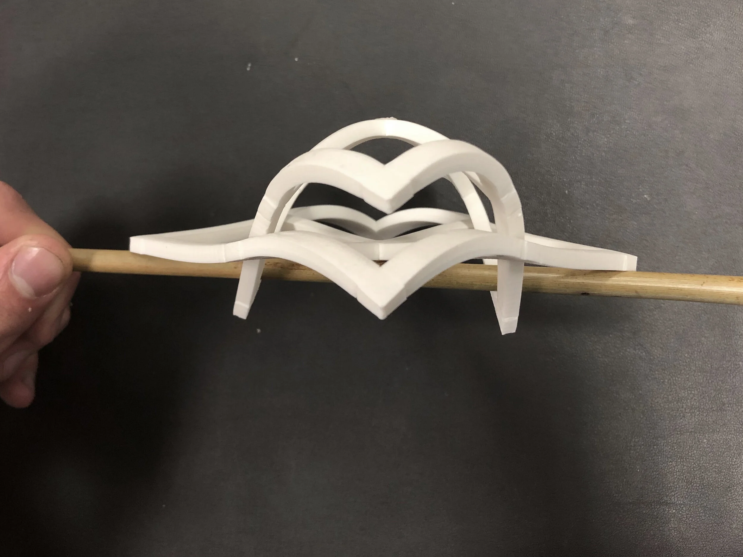
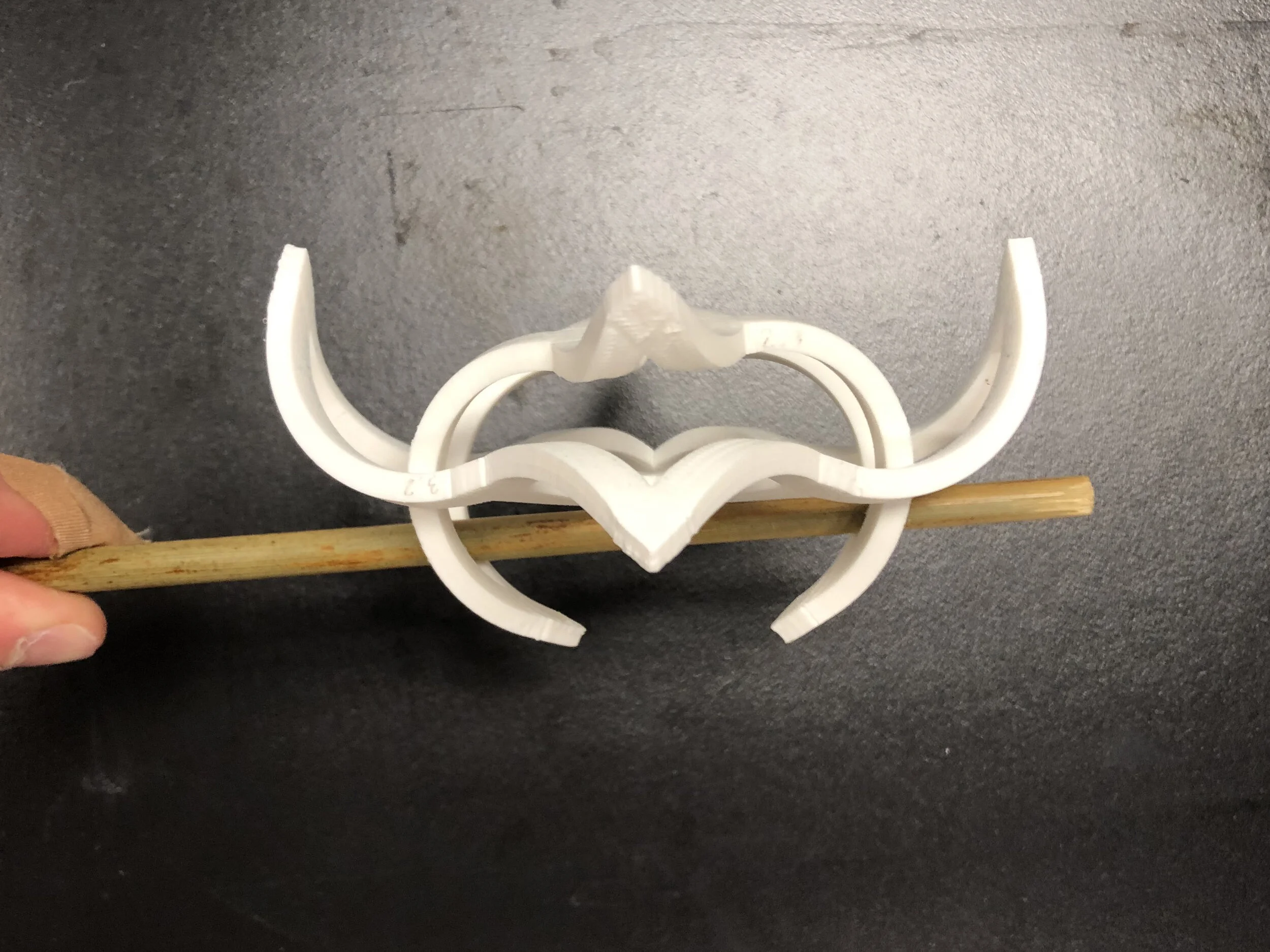
I determined that each bead-like unit would consist of two parts, with one outer and one inner piece intersecting each other. I made a quick mockup of my concept with post-it notes, and then got to work building it in the software. I was lucky to be working with the computer scientists at the Morphing Matter Lab who developed the software pipeline. They taught me how to assign stresses to each beam that would make them bend up or down (up is denoted by blue, and down by red).
Iterating
Once I got comfortable with the software, I was able to iterate on my concept. My early models had the rope justified to one end of the unit, locking the inner piece in place. However, for the final model I transitioned to having the rope go evenly through the middle of the two pieces, so that the stress would be distributed evenly.
Final Unit Design
Interactive Simulation of Unit
An amazing feature of the software pipeline I was working with was that once I had drawn my two-dimensional grid, the program simulated a 3D model of the part post-triggering with 99% accuracy. So, I could view an interactive model of my designs and see how the pair of parts fit together. It took some time to figure out how changes to the 2D drawing would affect the simulated result, but eventually I built up enough intuition about the program that I could achieve the right results.
Fabrication - Final Unit Design
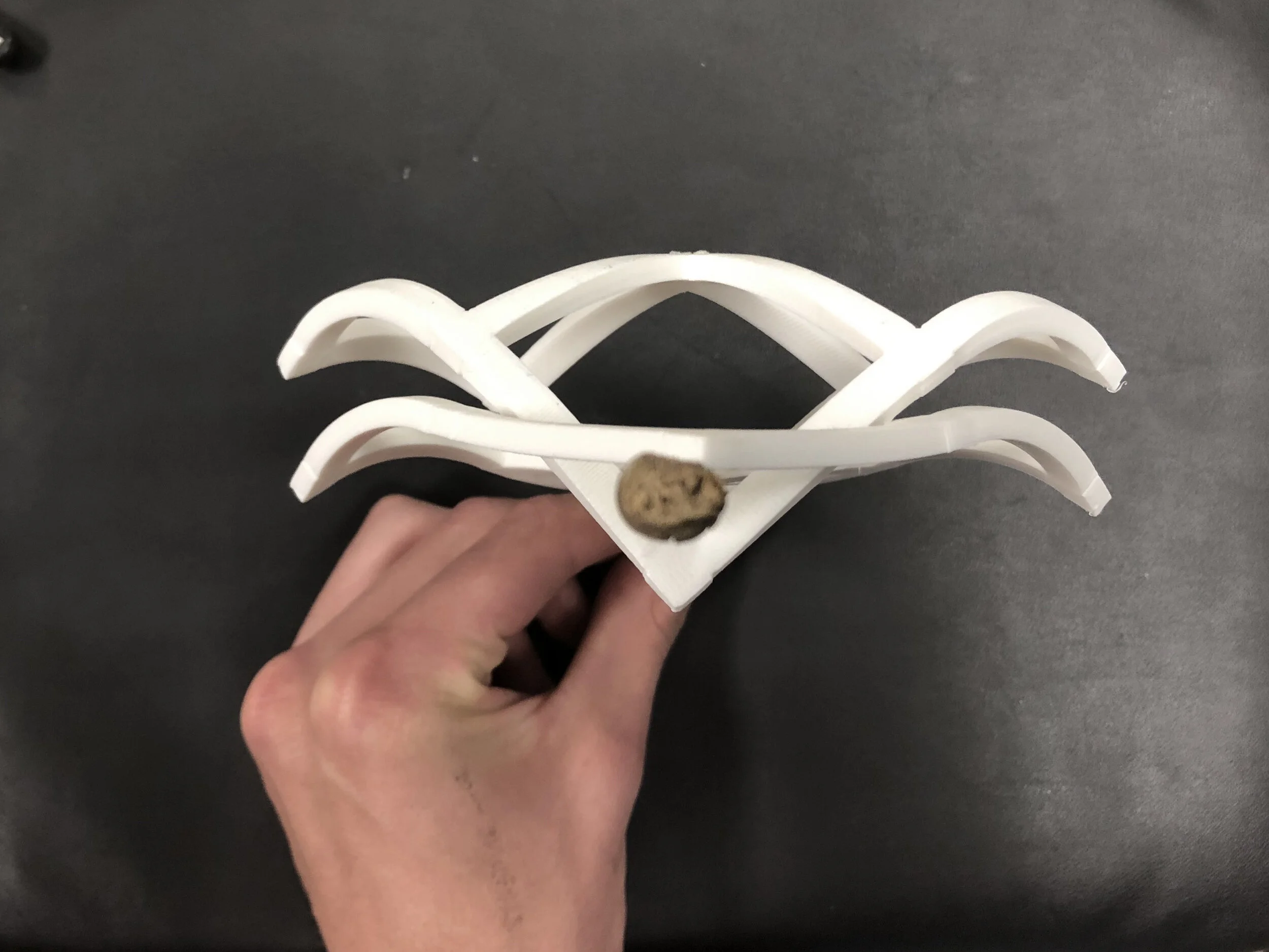
Now that I had the unit design finalized, I fabricated the first of many final parts. As mentioned, they are 3D-printed as flat, dimensional parts made up of interconnected beams with embedded tension determined by the software. To trigger the shape change, the parts are suspended in 80°C water for a few minutes.
Visualizing Assembly
Once I had a unit fabricated, I traced its outline onto paper and made multiples to look at different potential sizes for the assembly. I settled on a size of ten units per row, which would work out to be about an 18” diameter cylinder.
Rendering Assembly
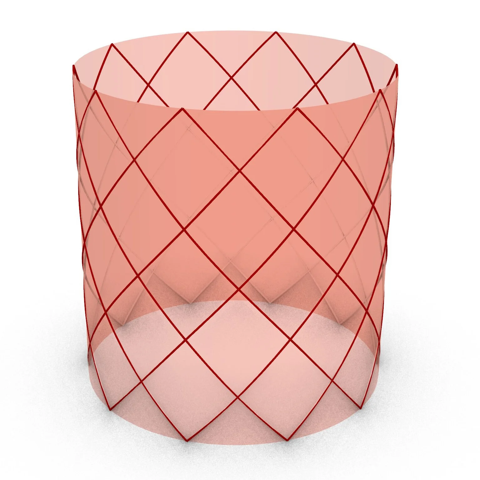
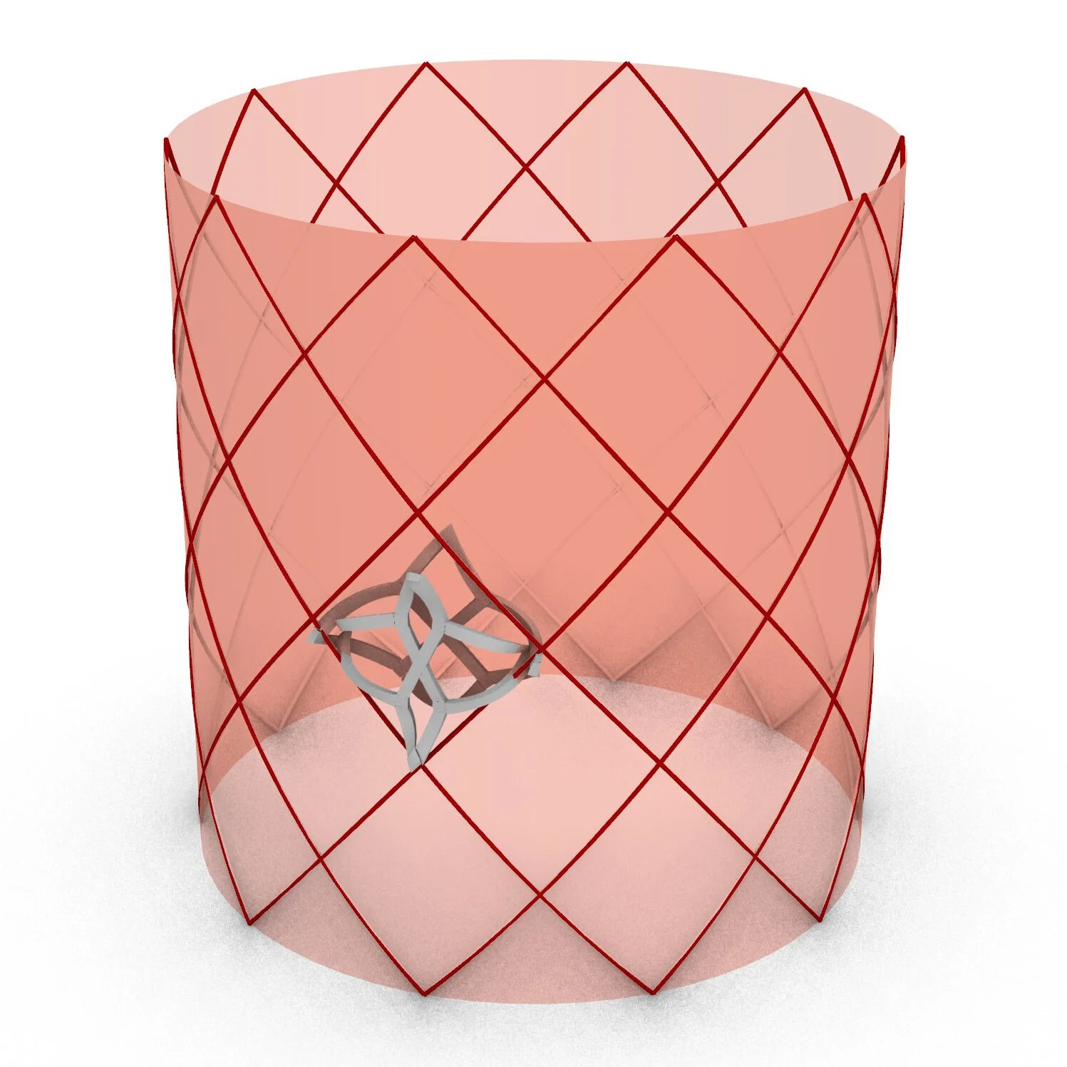
After I decided on the final proportions of the cylinder, my CS partners took the simulated unit file and used it to render the entire assembly. For the height of the structure we agreed on six layers, as that was the most it was feasible for us to fabricate while also being enough to adequately demonstrate the concept.
Final Rendering - Six-Layer Assembly
Batch Fabrication
We then moved on to batch printing and triggering all the pieces we would need. To speed things up we printed nine parts at a time and triggered four at a time. Still, fabricating all 120 parts took weeks of work.
Weaving Aggregate Form
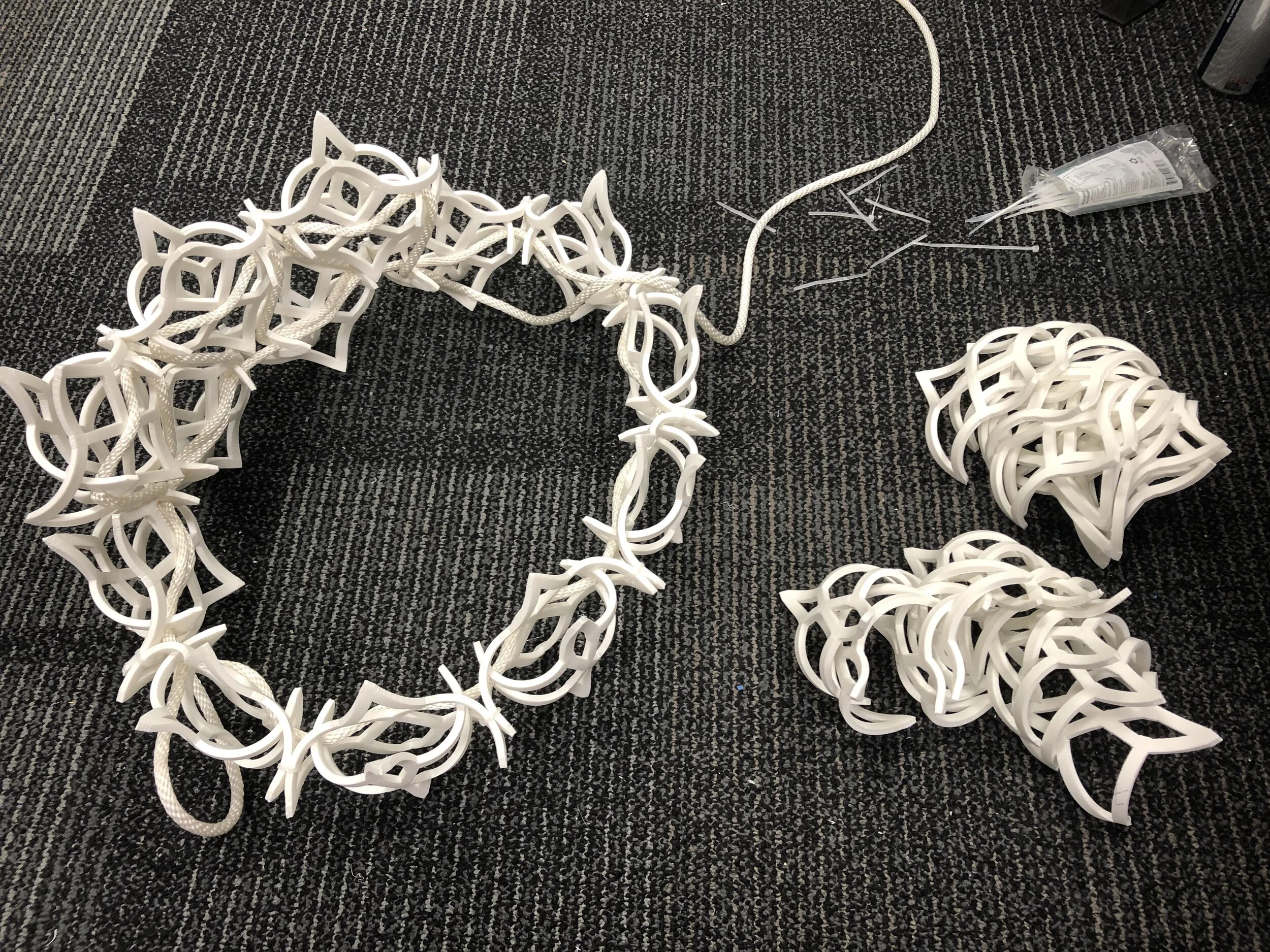
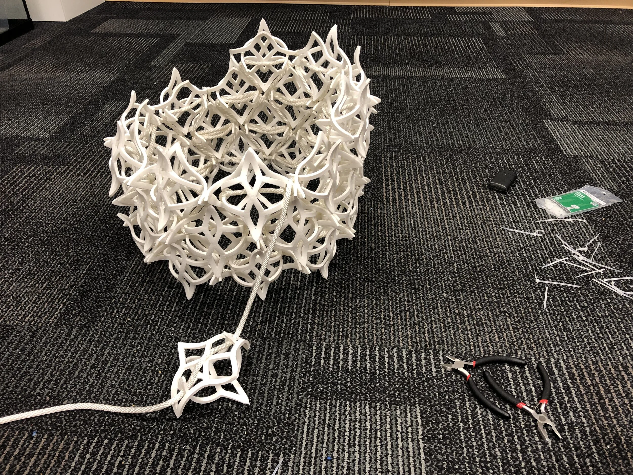
After getting all the parts made, it was finally time to weave them together. I tested many different types of rope to find the appropriate size, and decided on white to make the aggregate form feel homogenous. As I started to weave, I realized the units needed a bit more help staying aligned with the others on their row. So, I used clear zip ties to connect the outer units to each other. These worked very well, and were barely noticeable.
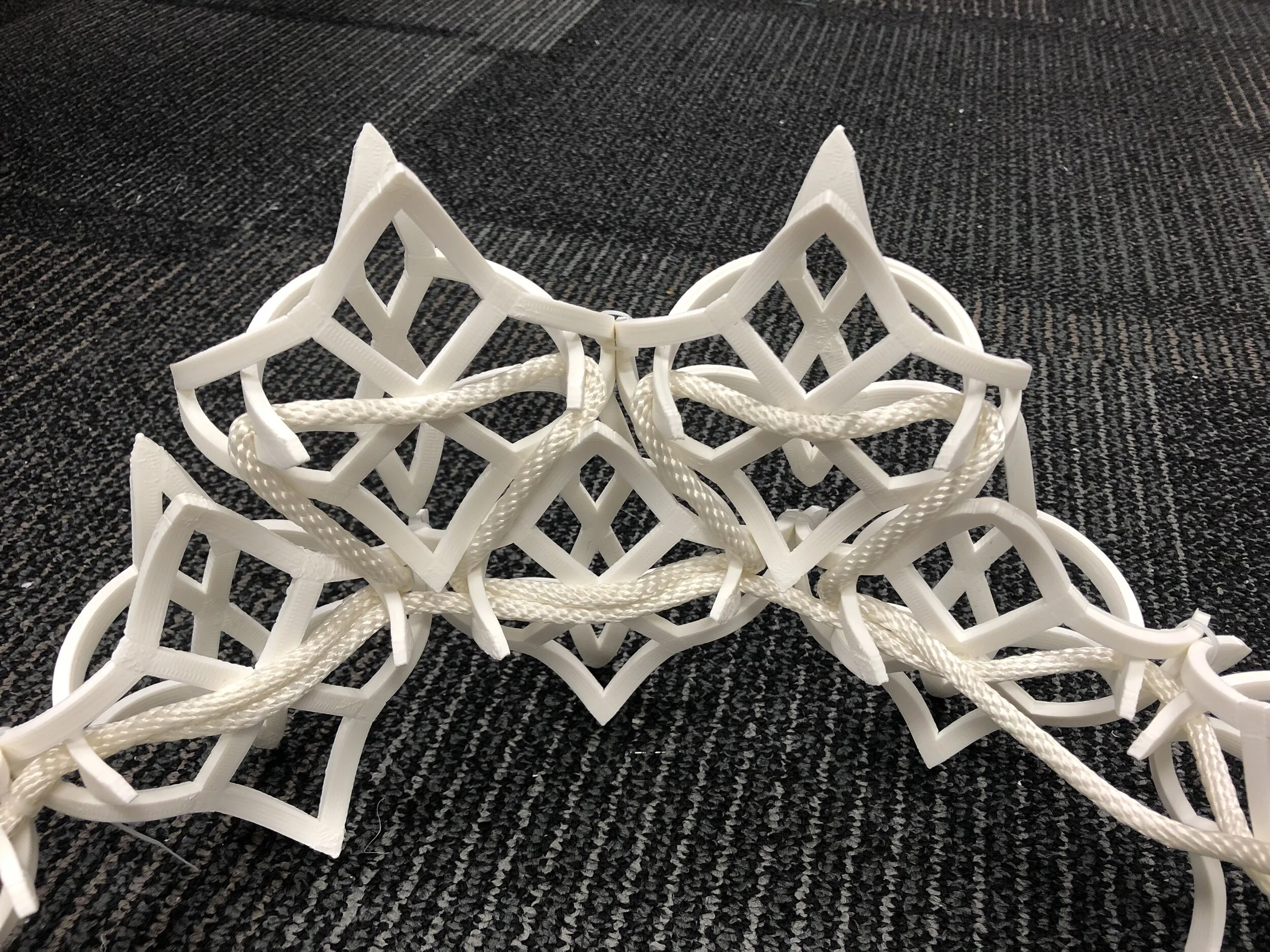
Testing rope thickness—it passes through each pair twice (and three times through pairs on transition up to a new row)
Materials ready for weaving: final batch of 120 PLA parts, 100ft of rope, and clear zip ties
Table - Version 1
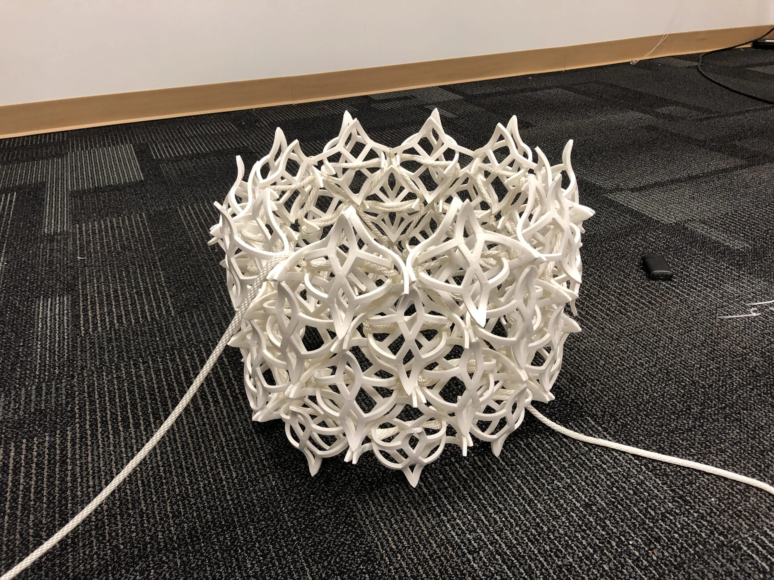
I was thrilled to find that my concept had succeeded with only minor adjustments to the assembly method. I ordered a glass tabletop to set onto the structure, so it would still be visible underneath. I knew that the structure would likely need something to act as an intermediary between it and the tabletop, but nonetheless I wanted to see the first iteration of the table be purely the aggregate form with a surface resting on top.
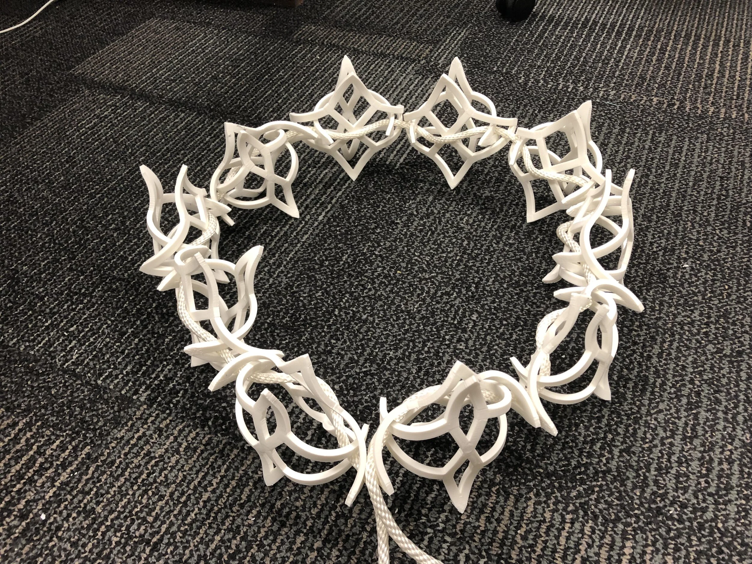
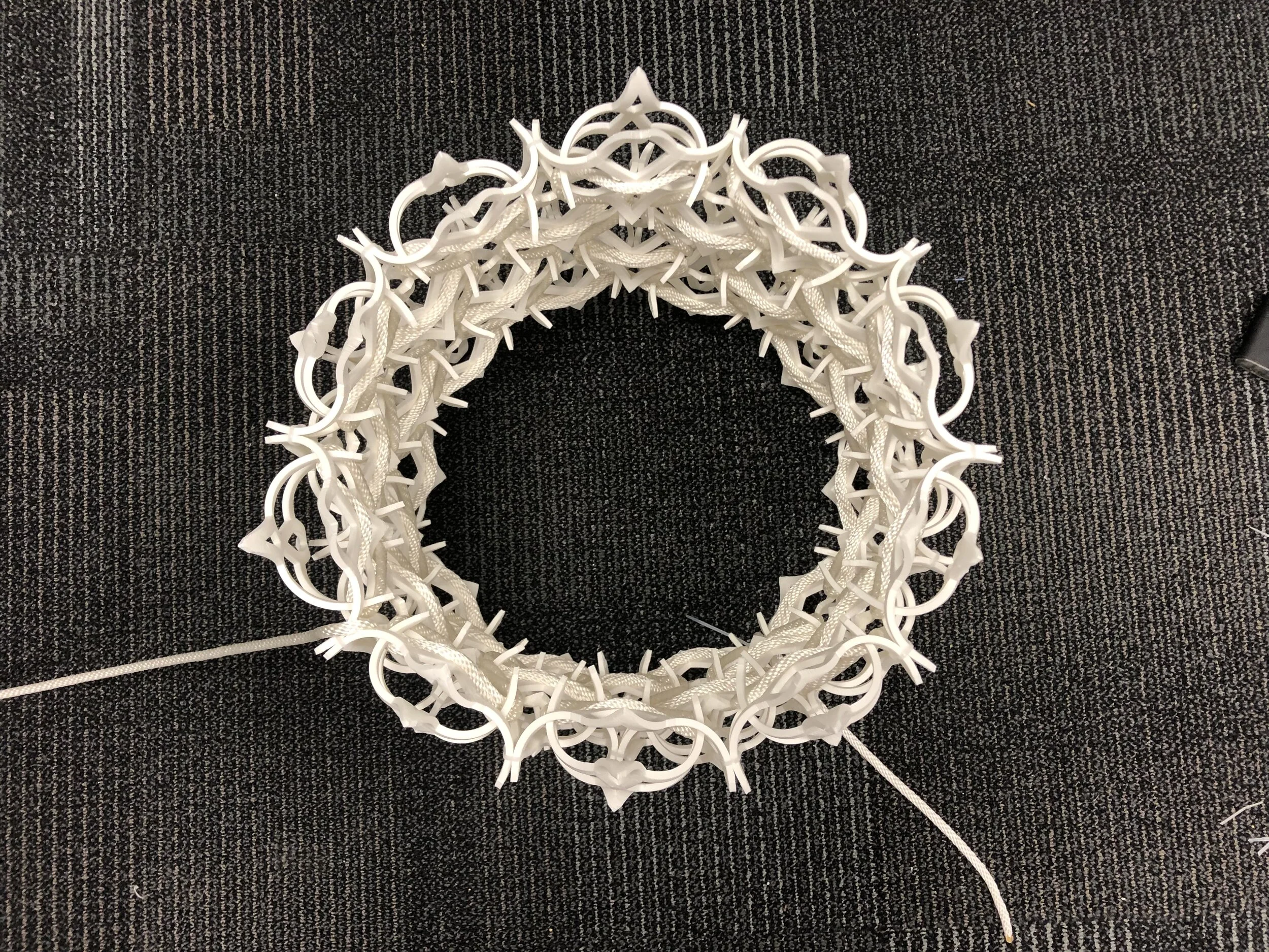
Finished aggregate form—six layers with white nylon rope
Tempered glass countertop—24” diameter, 1/2” thick
Furniture Design Exploration
I soon moved on to exploring a woodworking component to bring the table to life as a fully realized, functional furniture piece. Initially I was thinking (very traditionally) about giving the table legs, but soon realized it needed a form factor that referenced the design of the woven structure. In keeping with the ten-unit layer size, I decided to build two wooden decagons that would fit in between the inner and outer parts of the assembly. I worked on making foamcore templates to determine the right size for the wooden rings.
Final drawing of concept outlining relationship between woven structure and decagons
Testing out decagon templates on woven structure
Determining Proportions
I used Solidworks to mock up different proportional relationships between the assembly and the two wooden rings. I decided not to make the two identical to each other, but instead to make one 4” tall and the other 5” tall, to give the overall form hierarchy. I also tested out color, and landed on cherry wood as the best aesthetic to pair with the PLA.
Full-scale drawings of final two options for table size
Mockup of table/tabletop based on drawing, relative to average chair height
Crafting Wooden Decagons
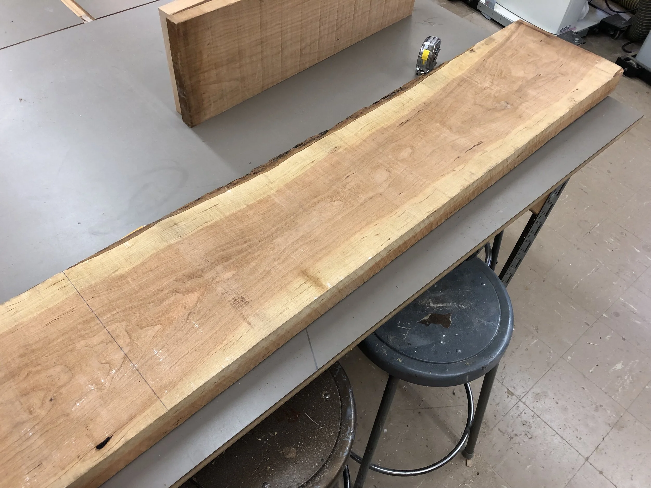
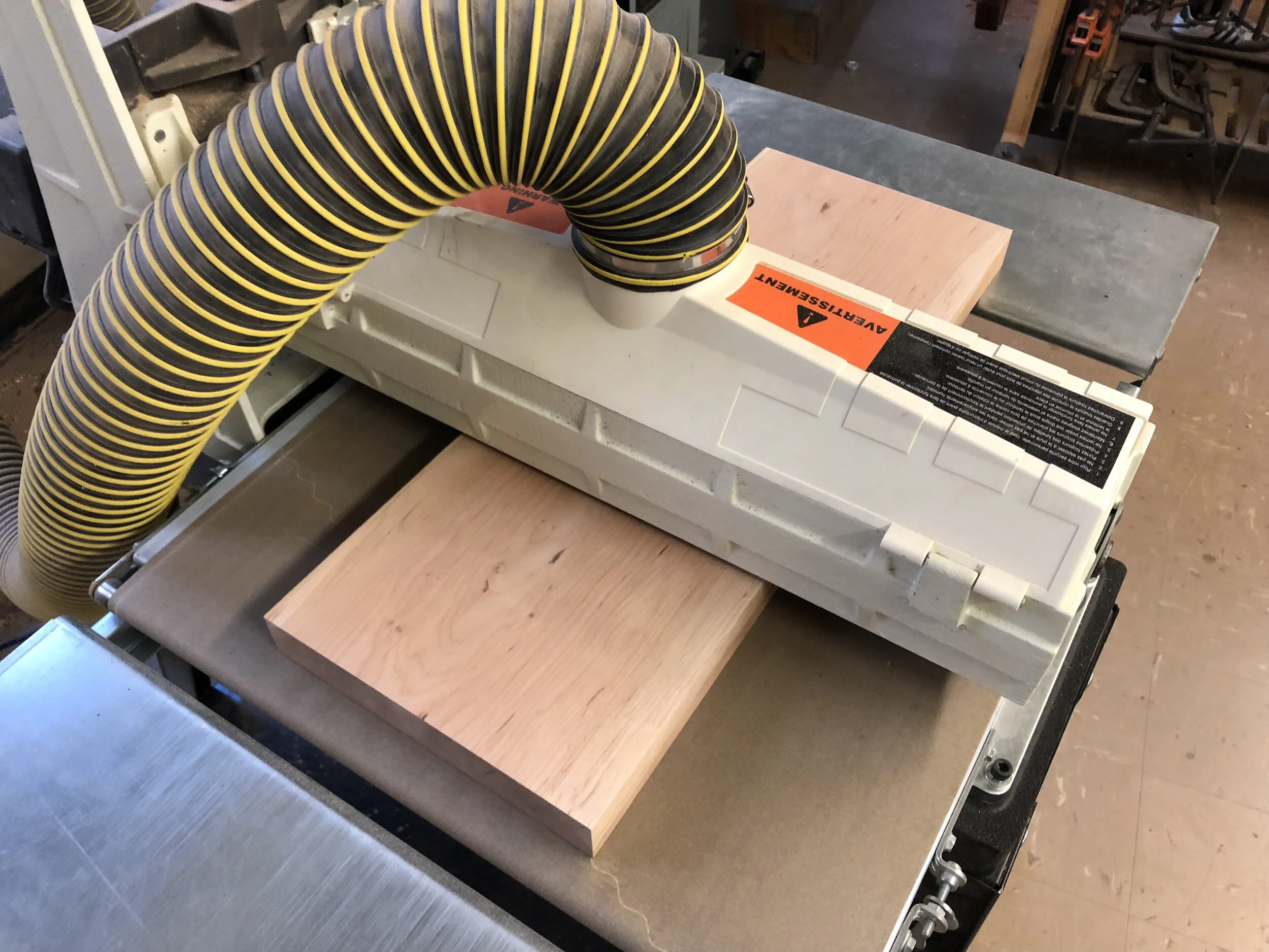
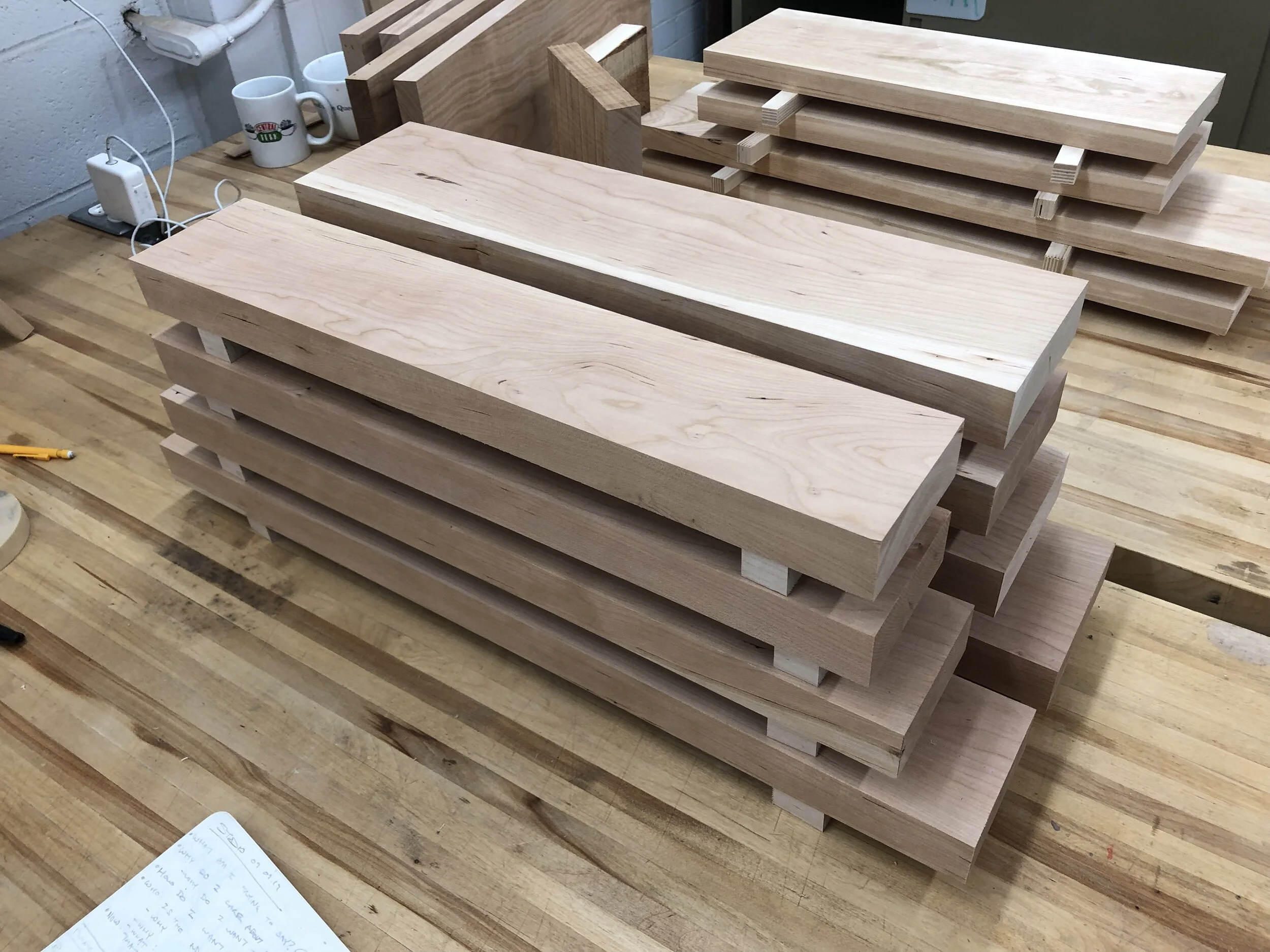
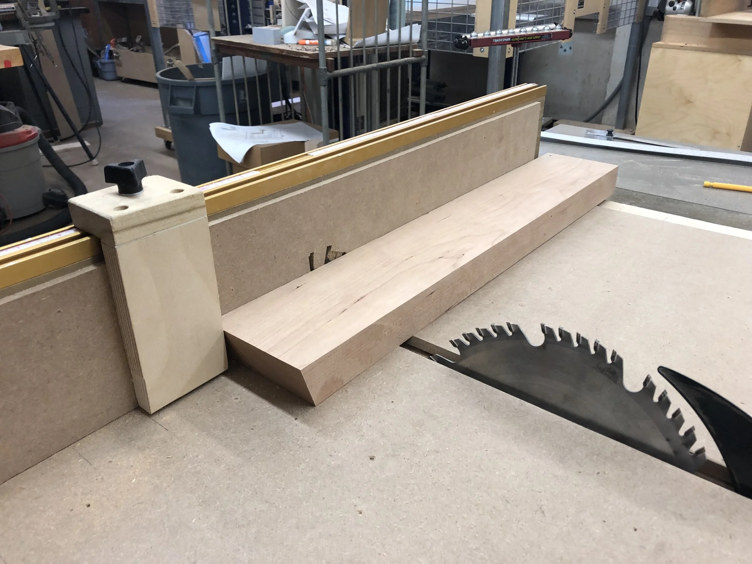
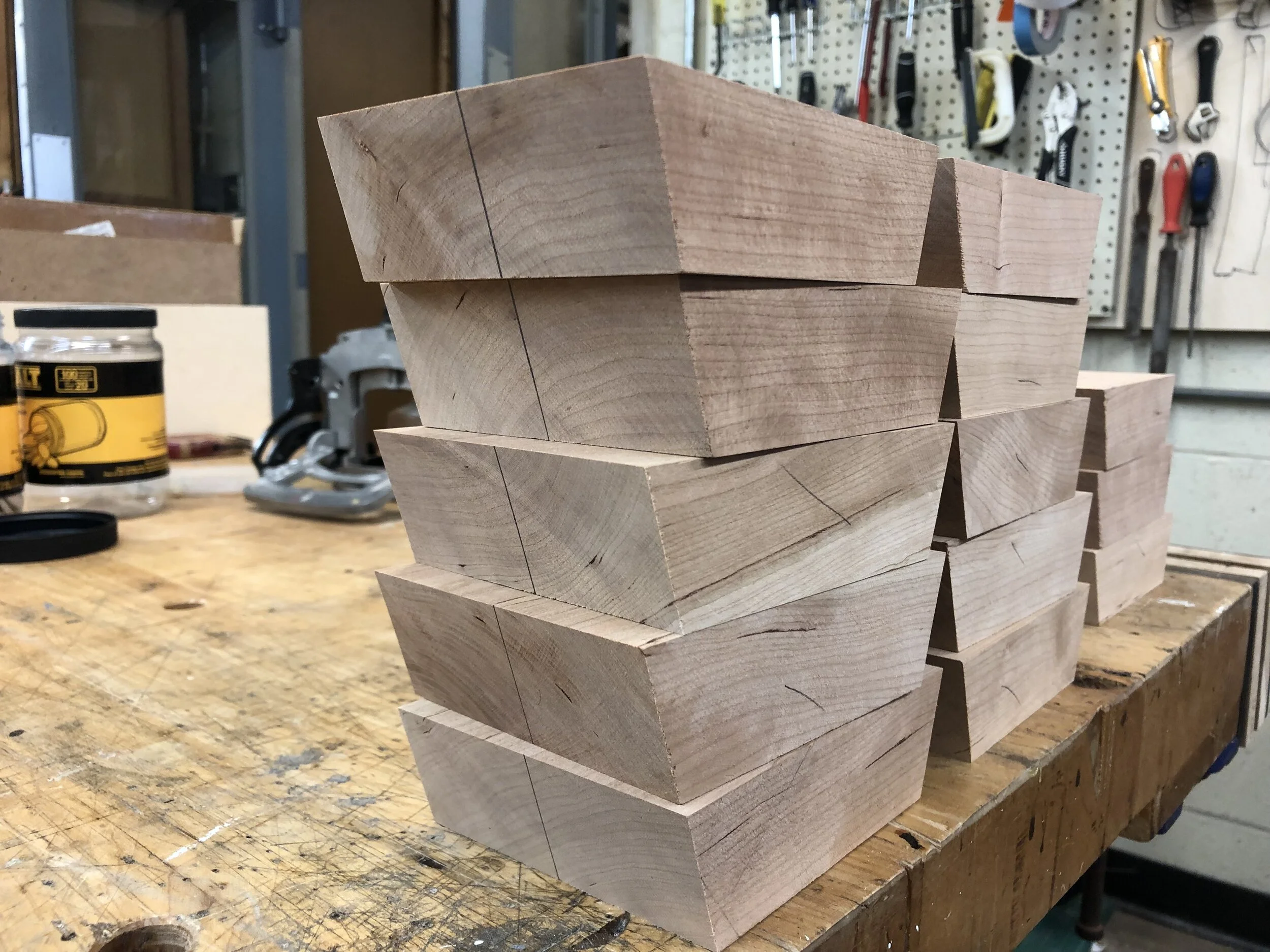
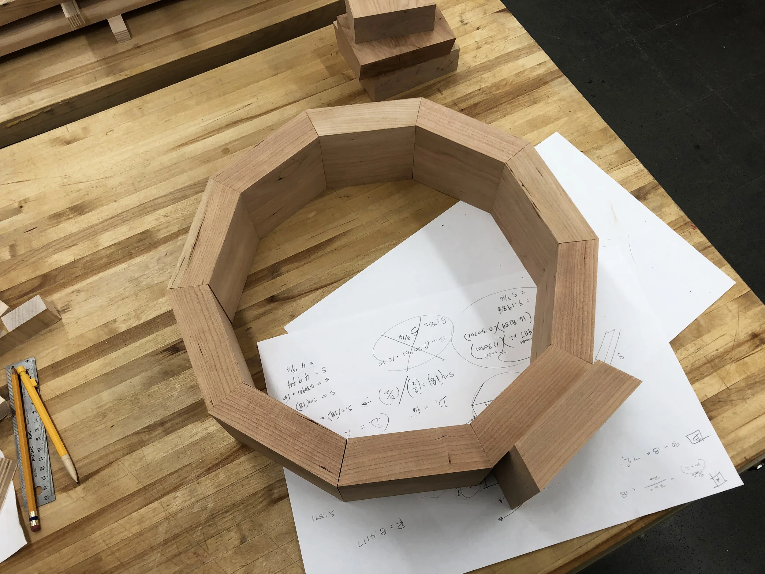
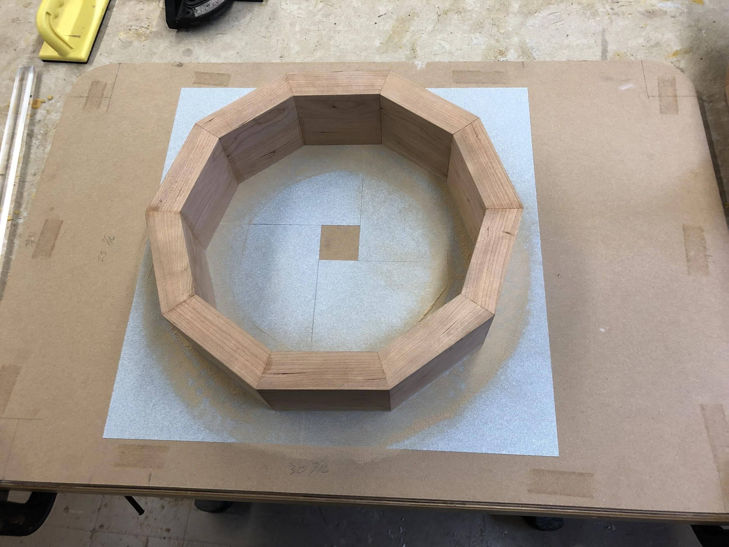
I then moved on to the woodworking phase. For the project I selected a 10ft plank of 8/4 cherry to work with. I chopped it up, planed it down, cut it to the proper widths, and left it to cure. Then, I made jig for the table saw to cut the precise angles into the pieces that would allow them to join together into the decagon shape.
I tested the dry assembly of the ring against the edge of the woven assembly to be sure it would still fit. I realized I would have to let some slack into the rope so the units could open up to accept the wooden rings.
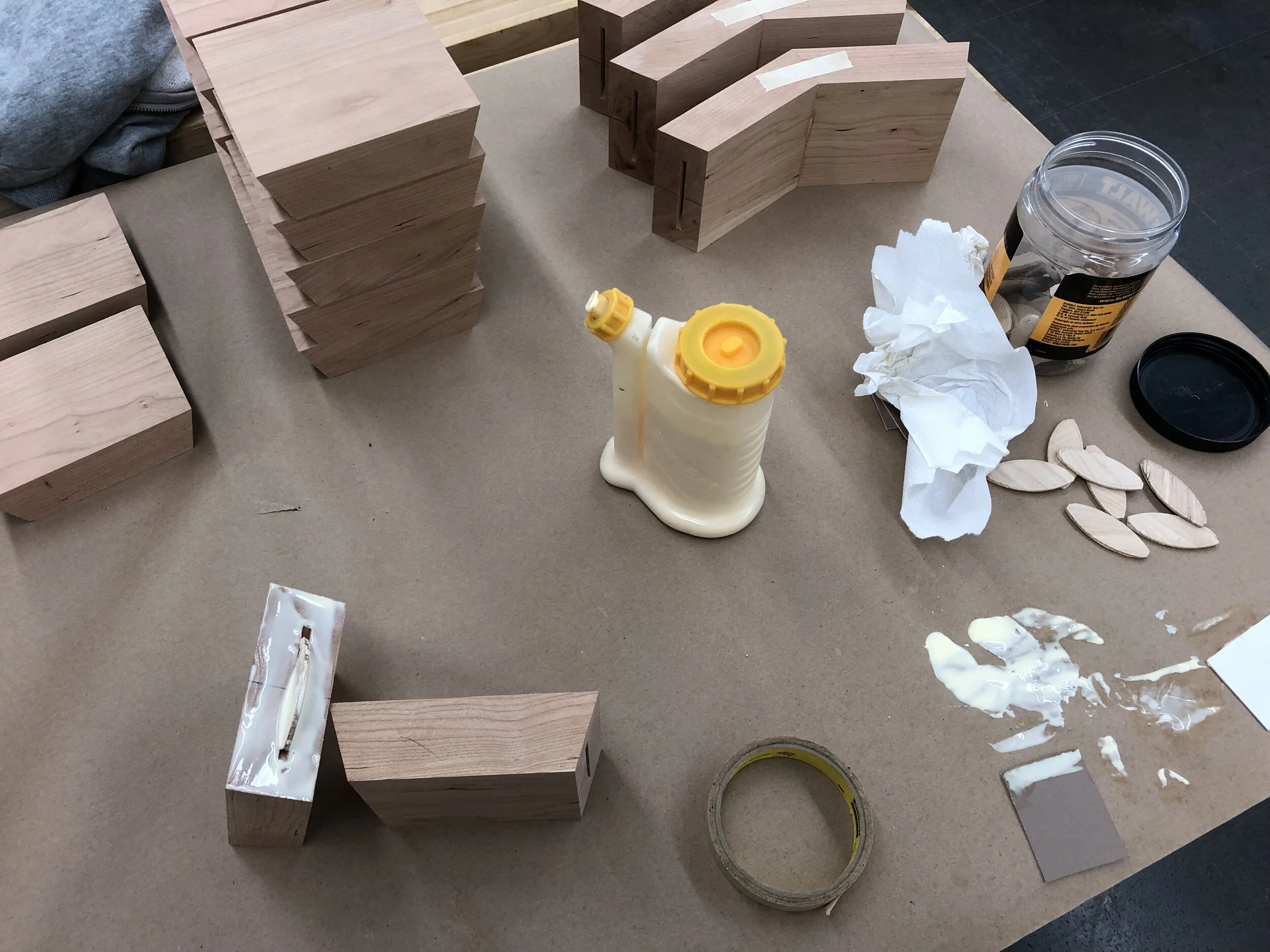
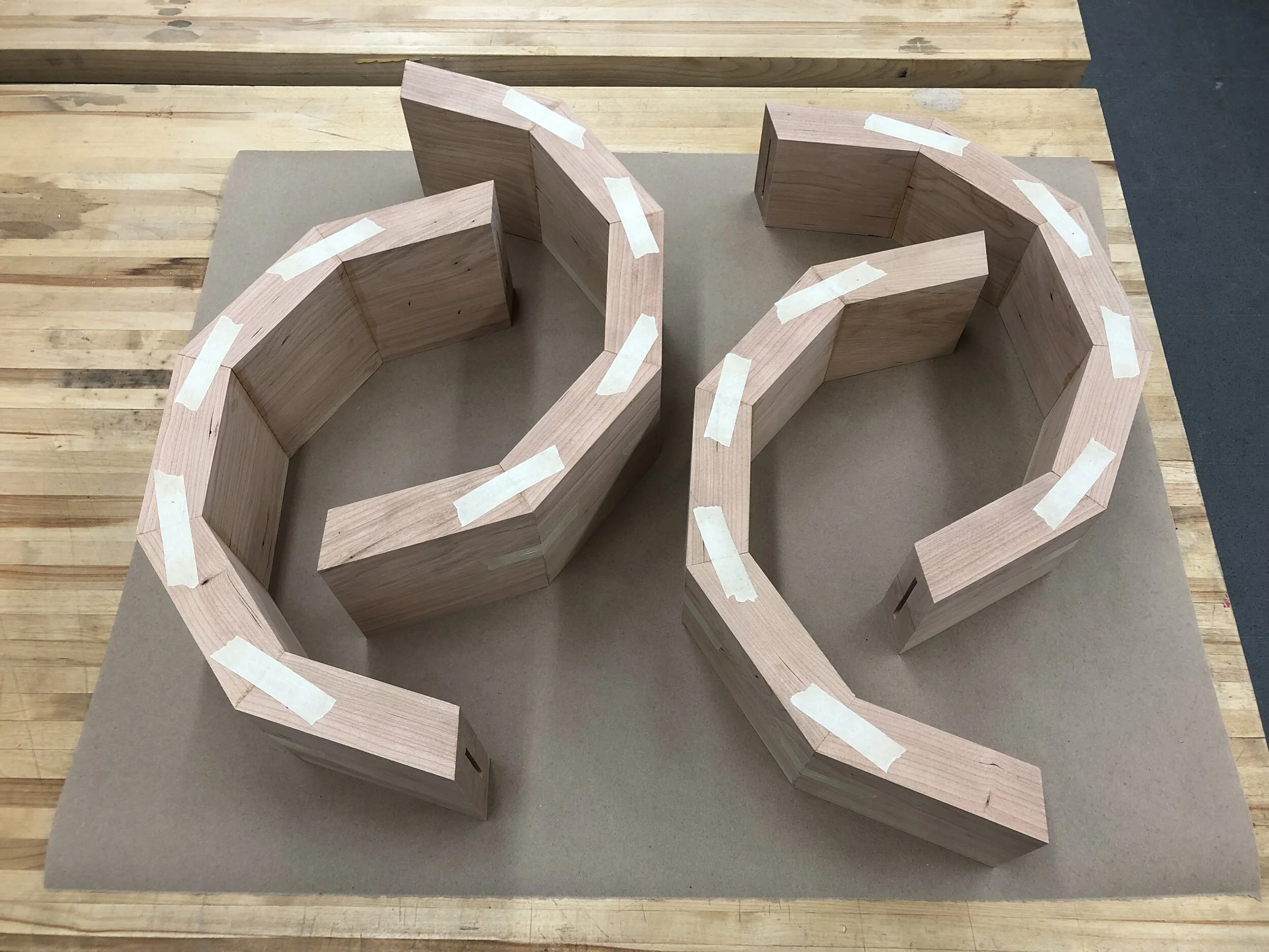
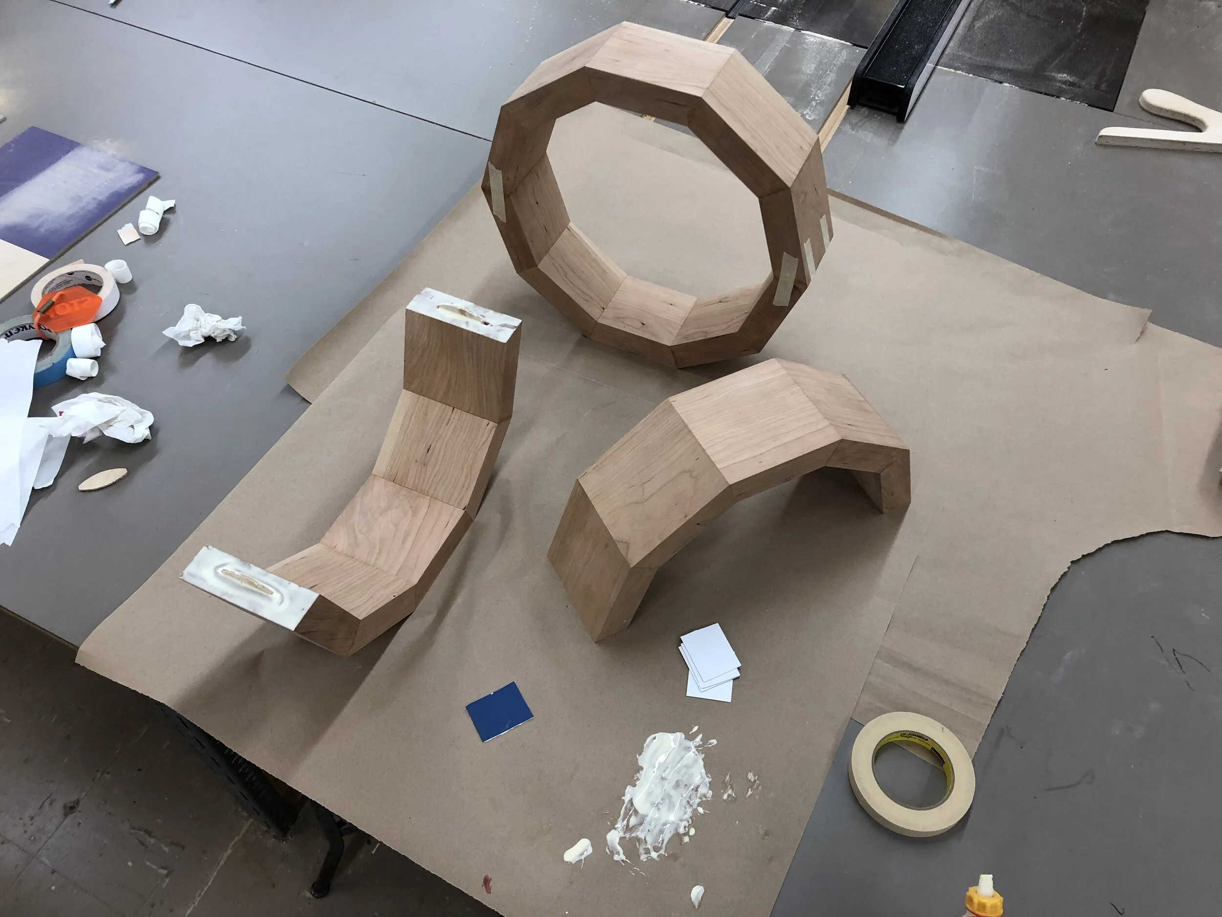
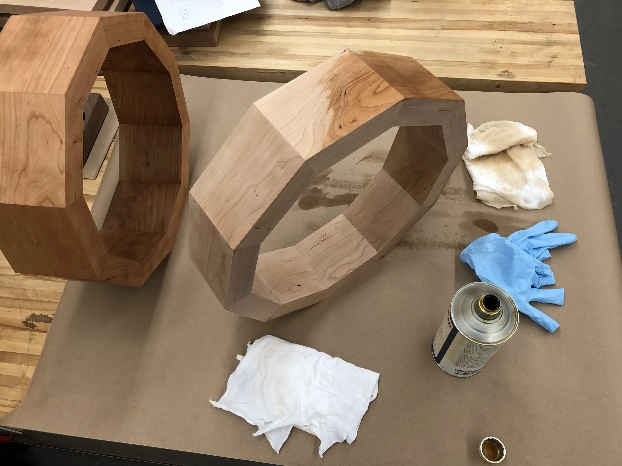
Next, I cut biscuit joints into all twenty pieces to ensure the rings would be strong. I glued up the sides in four pairs first, leaving two pieces independent. I then glued up assemblies of five sides and left those to dry. After a day, I glued the two pairs of halves together. All that was left was extensive sanding with custom blocks, and applying a finish.
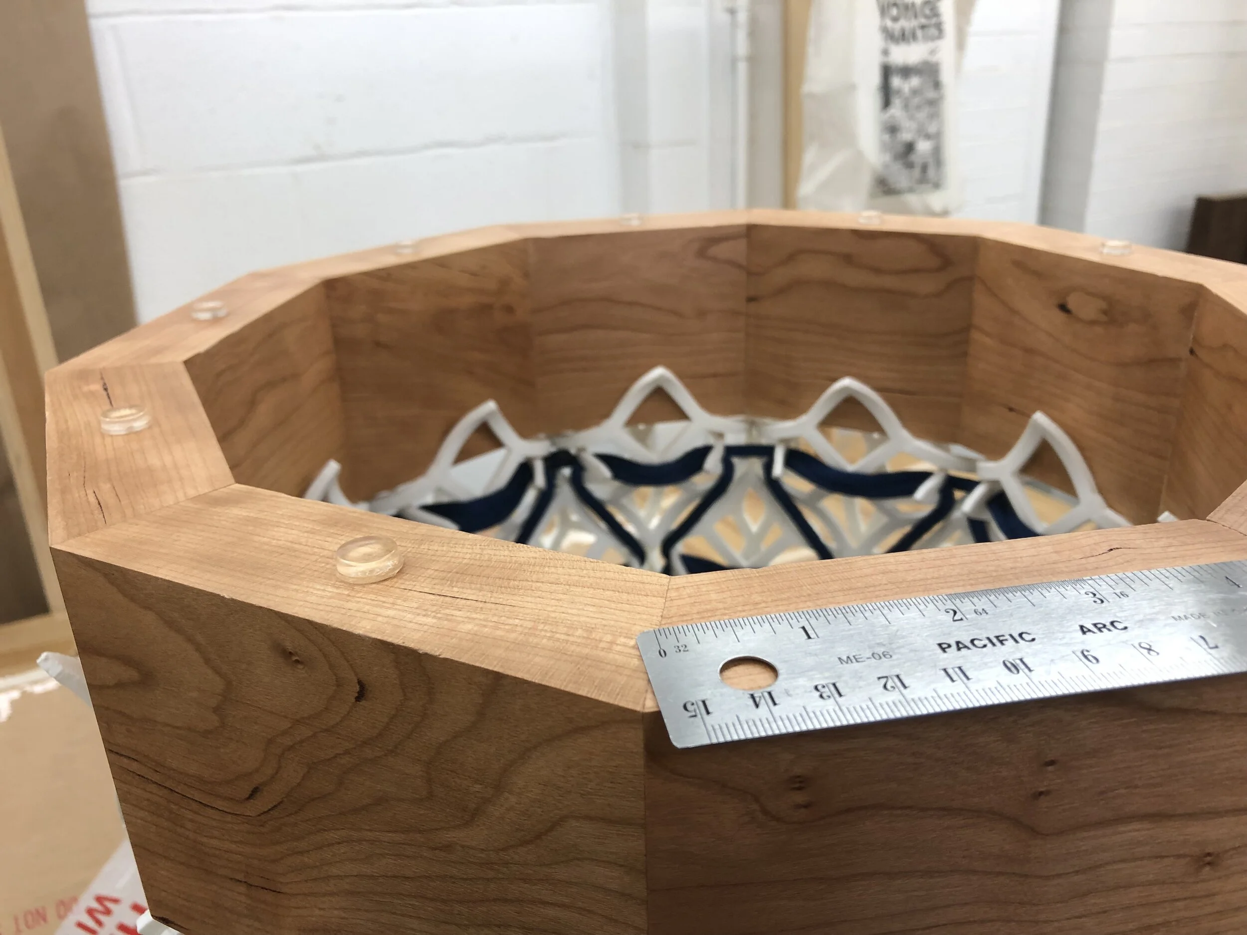
For the final piece I decided to reweave the structure with a finer, navy rope. This provided contrast with the white PLA that helped to accent the weave pattern. It also complements the warm tones of the cherry very well.
Last was assembling the table. It took some experimenting to get the rings fit in place snug and level without damaging the wood. Once in place, I tightened the rope and cut it off. I applied protective pads to the top of the ring to elevate the glass tabletop. Getting the top centered was more challenging than expected, but eventually I got the hang of it by standing directly above the table.
Signing and Dating Table
At the advice of a woodworking mentor, I decided to sign the table on the underside of the top ring—this way it would bear my mark but not be visible from a normal viewing perspective. I wrote out my name and date, made it a vector, and laser-etched the wood.
Final
The final form is an ethereal monument of a table—a peculiar yet elegant union of old and new materials and form language. From the outside, the almost chaotic aggregate form is framed by the decagons, and looking inward reveals clearly the pattern of the weave. This project was a challenging yet rewarding investigation of unifying different ways of making, and I’m satisfied by how I got everything to work together aesthetically and functionally.

